STM32 Board Bringup — From First Power-On to Full Verification
Complete bringup process for a custom STM32 board: first power-on, LED blink, peripheral verification, integration testing, and HAL function reference.
Board Bringup
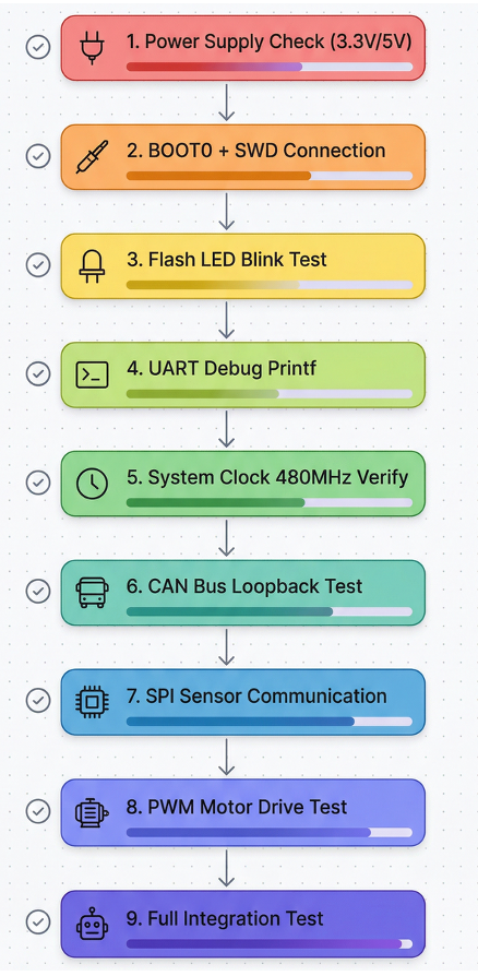 Board bringup 9-step flowchart
After building the board, this is the process of testing each peripheral one by one to verify correct operation. Never test everything at once — if something breaks, you won't be able to find the cause.
8.1 Step-by-Step Test Order
┌─────────────────────────────────────────────────┐
│  Step 1: Power Check                             │
│  → Measure VDD, VDDA, VCAP voltages             │
│  → Verify no shorts                              │
├─────────────────────────────────────────────────┤
│  Step 2: Clock Check                             │
│  → Verify HSE crystal oscillation               │
│  → Output clock on MCO pin and measure with     │
│    oscilloscope                                  │
├─────────────────────────────────────────────────┤
│  Step 3: LED Test (GPIO Output)                  │
│  → Blinking LED = power + clock + Flash + GPIO  │
│    all working                                   │
├─────────────────────────────────────────────────┤
│  Step 4: UART Test (PC Communication)            │
│  → Verify printf output                          │
│  → Bidirectional echo test                       │
├─────────────────────────────────────────────────┤
│  Step 5: CAN Test                                │
│  → Loopback mode (send to self)                  │
│  → Test with external CAN device                 │
├─────────────────────────────────────────────────┤
│  Step 6: SPI Test                                │
│  → Check SCK/MOSI waveforms with logic analyzer  │
│  → Data exchange with Coms MCU                   │
├─────────────────────────────────────────────────┤
│  Step 7: ADC Test                                │
│  → Apply known voltage (e.g. 1.65V) and read    │
│  → Check all channels in sequence                │
├─────────────────────────────────────────────────┤
│  Step 8: PWM Test                                │
│  → Verify frequency/duty cycle with oscilloscope │
│  → Check waveform before connecting motor driver │
├─────────────────────────────────────────────────┤
│  Step 9: Integration Test                        │
│  → Run all peripherals simultaneously            │
│  → Measure 500Hz control loop timing             │
└─────────────────────────────────────────────────┘
8.2 Step 1: Power Check
Before applying power:
- Use a multimeter to measure resistance between VDD-VSS and VDDA-VSSA → check for shorts
- Visually inspect PCB solder joints (bridges, cold joints, etc.)
After applying power:
| Pin | Expected Voltage | Acceptable Range | Notes |
|---|---|---|---|
| VDD (multiple pins) | 3.3V | 3.0~3.6V | Digital power |
| VDDA | 3.3V | 3.0~3.6V | Analog power (watch for noise) |
| VREF+ | 3.3V | = VDDA | ADC reference voltage |
| VCAP1 | ~1.2V | automatic | Internal regulator output, connect 1uF cap |
If VCAP1 is not ~1.2V, the internal regulator is not working → the core cannot operate. Causes: capacitor missing on VCAP pin, or VDD power issue.
8.3 Step 2: Clock Check
Verify the clock is working correctly before the LED test:
/* Enable MCO1 output in CubeMX: RCC → MCO1 → HSE */
/* Output 8MHz clock on PA8 (MCO1 pin) → measure with oscilloscope */

/* Or configure directly in code: */
HAL_RCC_MCOConfig(RCC_MCO1, RCC_MCO1SOURCE_HSE, RCC_MCODIV_1);
// If you see an 8MHz square wave on PA8, HSE crystal is working!

HAL_RCC_MCOConfig(RCC_MCO1, RCC_MCO1SOURCE_PLL1QCLK, RCC_MCODIV_4);
// Output PLL1Q / 4 → verify 240MHz/4 = 60MHz
8.4 Step 3: LED Test
Use the LED blink code from section 4.7.
Checklist:
- Does the LED blink at exactly 500ms intervals?
- Do the other GPIO LEDs work too? (each RGB LED color)
- Can you download code and debug via SWD debugger?
8.5 Step 4: UART Test
/* USER CODE BEGIN 2 */
printf("AR_Walker STM32 Board Test\r\n");
printf("SYSCLK: %lu MHz\r\n", HAL_RCC_GetSysClockFreq() / 1000000);
printf("HCLK:   %lu MHz\r\n", HAL_RCC_GetHCLKFreq() / 1000000);
/* USER CODE END 2 */

while (1)
{
    /* USER CODE BEGIN 3 */
    // Echo test: retransmit received data back
    uint8_t rx_byte;
    if (HAL_UART_Receive(&huart3, &rx_byte, 1, 10) == HAL_OK)
    {
        HAL_UART_Transmit(&huart3, &rx_byte, 1, 10);
    }
    /* USER CODE END 3 */
}
Verify on PC: Connect with a serial terminal (PuTTY, minicom, Arduino Serial Monitor) at 115200 baud.
8.6 Step 5: CAN Loopback Test
/* Set FDCAN1 Mode to "Internal LoopBack" in CubeMX */
/* → Send a message to yourself without an external CAN transceiver and verify reception */

void CAN_LoopbackTest(void)
{
    FDCAN_TxHeaderTypeDef tx_header;
    FDCAN_RxHeaderTypeDef rx_header;
    uint8_t tx_data[8] = {0x01, 0x02, 0x03, 0x04, 0x05, 0x06, 0x07, 0x08};
    uint8_t rx_data[8] = {0};

    tx_header.Identifier = 0x123;
    tx_header.IdType = FDCAN_STANDARD_ID;
    tx_header.TxFrameType = FDCAN_DATA_FRAME;
    tx_header.DataLength = FDCAN_DLC_BYTES_8;
    tx_header.BitRateSwitch = FDCAN_BRS_OFF;
    tx_header.FDFormat = FDCAN_CLASSIC_CAN;

    // Transmit message
    HAL_FDCAN_AddMessageToTxFifoQ(&hfdcan1, &tx_header, tx_data);
    HAL_Delay(10);

    // Verify message received
    if (HAL_FDCAN_GetRxMessage(&hfdcan1, FDCAN_RX_FIFO0, &rx_header, rx_data) == HAL_OK)
    {
        if (rx_header.Identifier == 0x123 && rx_data[0] == 0x01)
        {
            printf("CAN Loopback Test: PASSED!\r\n");
        }
    }
    else
    {
        printf("CAN Loopback Test: FAILED!\r\n");
    }
}
8.7 Steps 6~8: SPI, ADC, PWM Tests
Test each independently. Order doesn't matter, but check one at a time.
SPI Test:
// Loopback: connect MOSI to MISO with a jumper wire
uint8_t tx = 0xA5, rx = 0x00;
HAL_SPI_TransmitReceive(&hspi1, &tx, &rx, 1, 100);
printf("SPI Loopback: TX=0x%02X, RX=0x%02X %s\r\n",
       tx, rx, (tx == rx) ? "PASS" : "FAIL");
ADC Test:
// Connect 1.65V (VDD/2) to PA0, then:
HAL_ADC_Start(&hadc1);
HAL_ADC_PollForConversion(&hadc1, 100);
uint32_t adc_val = HAL_ADC_GetValue(&hadc1);
float voltage = adc_val * 3.3f / 4096.0f;
printf("ADC IN0: %lu (%.3f V, expected ~1.65V)\r\n", adc_val, voltage);
PWM Test:
// Output 1kHz, 50% duty PWM on PE9
HAL_TIM_PWM_Start(&htim1, TIM_CHANNEL_1);
// → Measure PE9 with oscilloscope: verify 1kHz, 50%
// Duty cycle change test:
__HAL_TIM_SET_COMPARE(&htim1, TIM_CHANNEL_1, 250);  // 25%
HAL_Delay(2000);
__HAL_TIM_SET_COMPARE(&htim1, TIM_CHANNEL_1, 750);  // 75%
8.8 Step 9: Integration Test
After all individual tests pass, run everything simultaneously:
/* 500Hz control loop (using TIM6 interrupt) */
// CubeMX: TIM6, Prescaler=239, Period=1999 → 240MHz/(240*2000) = 500Hz
// Use a 500Hz counter in the interrupt

volatile uint8_t control_loop_flag = 0;

void HAL_TIM_PeriodElapsedCallback(TIM_HandleTypeDef *htim)
{
    if (htim == &htim6)
    {
        control_loop_flag = 1;
    }
}

/* Inside main.c while(1) */
while (1)
{
    if (control_loop_flag)
    {
        control_loop_flag = 0;

        // Start timing measurement
        HAL_GPIO_WritePin(GPIOC, GPIO_PIN_8, GPIO_PIN_SET);  // Speed Check pin

        // 1. Read ADC (available immediately since it uses DMA)
        float torque_L = get_torque_left_Nm();
        float torque_R = get_torque_right_Nm();

        // 2. Check IMU data (latest value from completed DMA receive)
        float gyro_z = get_imu_gyro_z();

        // 3. Run control algorithm
        float cmd_L = controller_update(torque_L, gyro_z);
        float cmd_R = controller_update(torque_R, gyro_z);

        // 4. Send motor commands (CAN or PWM)
        CAN_SendMotorCommand(0x01, cmd_L);
        CAN_SendMotorCommand(0x02, cmd_R);

        // 5. Send status to Coms MCU via SPI
        SPI_SendStatus(torque_L, torque_R, cmd_L, cmd_R);

        // End timing measurement
        HAL_GPIO_WritePin(GPIOC, GPIO_PIN_8, GPIO_PIN_RESET);
    }
}
Integration Test Checklist:
- Is the HIGH period on the Speed Check pin (PC8) less than 2ms (= 500Hz period)? (control loop completes in time)
- Do all ADC channels read correct values?
- Is CAN TX/RX synchronized with the control loop?
- Does UART debug output not affect the control loop timing?
- Is SPI communication working correctly?
- Does it remain stable over extended runs (minutes to hours)?
HAL Function Reference
| Category | Function | Description |
|---|---|---|
| System | HAL_Init() |
HAL initialization, SysTick setup |
HAL_Delay(ms) |
Millisecond wait (blocking) | |
HAL_GetTick() |
Millisecond counter since system start | |
| GPIO | HAL_GPIO_Init(port, &init) |
GPIO initialization |
HAL_GPIO_WritePin(port, pin, state) |
Write pin output | |
HAL_GPIO_ReadPin(port, pin) |
Read pin state | |
HAL_GPIO_TogglePin(port, pin) |
Toggle pin | |
| UART | HAL_UART_Transmit(&h, data, len, timeout) |
Transmit (blocking) |
HAL_UART_Receive(&h, data, len, timeout) |
Receive (blocking) | |
HAL_UART_Transmit_DMA(&h, data, len) |
DMA transmit | |
HAL_UARTEx_ReceiveToIdle_DMA(&h, data, len) |
DMA receive (idle detection) | |
| SPI | HAL_SPI_TransmitReceive(&h, tx, rx, len, timeout) |
Transmit and receive |
HAL_SPI_TransmitReceive_DMA(&h, tx, rx, len) |
DMA transmit and receive | |
| ADC | HAL_ADC_Start(&h) |
Start ADC conversion |
HAL_ADC_Start_DMA(&h, data, len) |
Start DMA ADC | |
HAL_ADC_GetValue(&h) |
Read conversion result | |
| CAN | HAL_FDCAN_Start(&h) |
Start FDCAN |
HAL_FDCAN_AddMessageToTxFifoQ(&h, &hdr, data) |
Transmit message | |
HAL_FDCAN_GetRxMessage(&h, fifo, &hdr, data) |
Receive message | |
HAL_FDCAN_ConfigFilter(&h, &filter) |
Configure receive filter | |
| Timer | HAL_TIM_PWM_Start(&h, ch) |
Start PWM output |
__HAL_TIM_SET_COMPARE(&h, ch, val) |
Change PWM duty cycle | |
HAL_TIM_Base_Start_IT(&h) |
Start timer interrupt | |
| Clock | HAL_RCC_GetSysClockFreq() |
Get SYSCLK frequency |
HAL_RCC_GetHCLKFreq() |
Get AHB clock frequency |
References
| Resource | Description |
|---|---|
| STM32H743 Datasheet (DS12110) | Pinout, AF table, electrical characteristics |
| STM32H7 Reference Manual (RM0433) | Registers, peripheral operation details |
| STM32H7 HAL User Manual (UM2217) | HAL function API documentation |
| AN5293 | STM32H7 FDCAN usage guide |
| AN4031 | DMA controller usage guide |
| AR_Walker STM32_Setup/README.md | Multi-PC development environment, USER CODE management |
| AR_Walker STM32_Setup/project_structure.md | Monorepo project structure |
| AR_Walker Board.h | Current Teensy pin configuration (original mapping source) |
Last updated: 2026-04-06 Target chip: STM32H743VITx (LQFP-100) Project: AR_Walker (walking assist robot exoskeleton)
Previous post: STM32 Pin Mapping Strategy | Back to first post

Henry — Robot Education Founder
Engineer dedicated to democratizing robot education for everyone. From hardware bring-up to AI integration, I document real learning.
Comments
Loading comments...