STM32 Essential Peripherals — FDCAN, UART, SPI, ADC, PWM
Comprehensive guide to STM32 peripherals for robotics: FDCAN, UART, SPI, I2C, ADC, and PWM timers with HAL code examples.
Essential Peripherals for Robotics
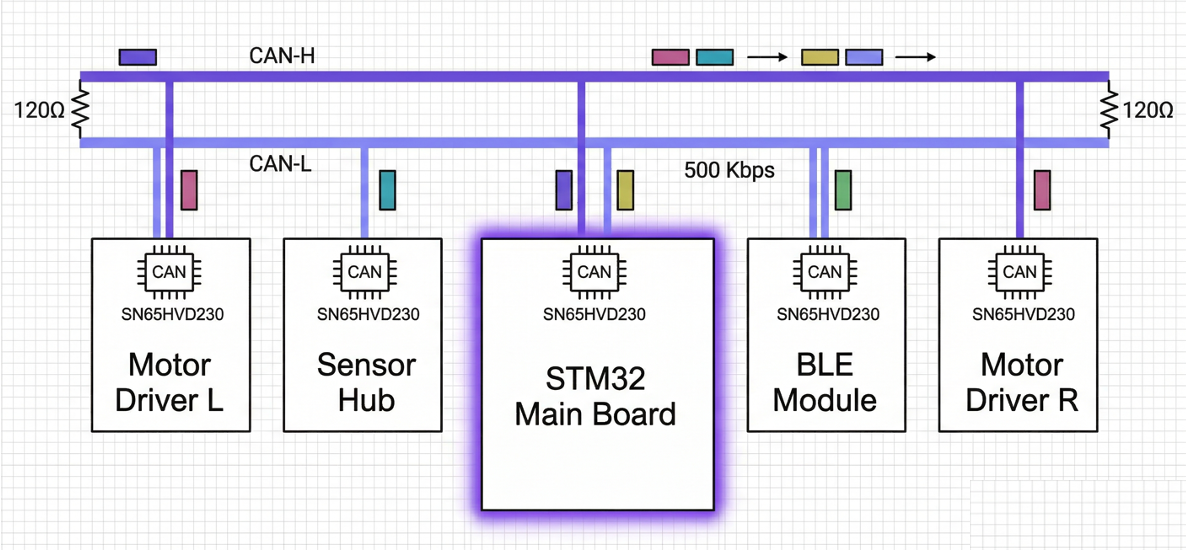 CAN bus communication topology
5.1 FDCAN (Motor CAN Communication)
The T-Motor units (AK60, AK70, AK80) in AR_Walker communicate over a CAN bus. The STM32H7 supports FDCAN (Flexible Data-rate CAN), which is backward-compatible with both classic CAN 2.0 and CAN FD.
CAN vs CAN FD Comparison
| Item | CAN 2.0 | CAN FD |
|---|---|---|
| Data length | Up to 8 bytes | Up to 64 bytes |
| Bit rate | Up to 1 Mbps | Nominal 1 Mbps + Data up to 8 Mbps |
| Current motor usage | CAN 2.0 | (expandable in the future) |
AR_Walker's T-Motor uses CAN 2.0 (1 Mbps, 8 bytes). The FDCAN peripheral is backward-compatible and can operate in CAN 2.0 mode.
FDCAN Pin Options (LQFP-100)
| Peripheral | TX Pin Options | RX Pin Options | AF |
|---|---|---|---|
| FDCAN1 | PD1, PA12, PB9 | PD0, PA11, PB8 | AF9 |
| FDCAN2 | PB13, PB6 | PB5, PB12 | AF9 |
Recommended AR_Walker mapping:
- FDCAN1: PD1 (TX), PD0 (RX) → AF9
- Rationale: Placing on Port D avoids conflicts with the ADC/SPI pins on Port A
CubeMX Configuration
- Connectivity → FDCAN1 → Enable
- Parameter Settings:
- Frame Format: Classic (CAN 2.0 mode)
- Mode: Normal (loopback is for testing only)
- Nominal Prescaler: 3
- Nominal Time Seg1: 13
- Nominal Time Seg2: 2
- Nominal Sync Jump Width: 1
- → Nominal Bit Rate = APB1_CLK / (Prescaler * (1 + Seg1 + Seg2))
- → 120MHz / (3 * (1+13+2)) = 120/48 = 2.5 Mbps... → needs adjustment
- Prescaler: 10, Seg1: 5, Seg2: 6 → 120/(10*(1+5+6)) = 1 Mbps
HAL Code Example
/* FDCAN initialization — auto-generated by CubeMX */
FDCAN_HandleTypeDef hfdcan1;
/* USER CODE BEGIN: filter setup + start */
void FDCAN1_Start(void)
{
FDCAN_FilterTypeDef filter;
filter.IdType = FDCAN_STANDARD_ID;
filter.FilterIndex = 0;
filter.FilterType = FDCAN_FILTER_MASK;
filter.FilterConfig = FDCAN_FILTER_TO_RXFIFO0;
filter.FilterID1 = 0x000; // accept all IDs
filter.FilterID2 = 0x000; // mask: ignore all bits (= accept everything)
HAL_FDCAN_ConfigFilter(&hfdcan1, &filter);
// Enable FIFO0 receive interrupt
HAL_FDCAN_ActivateNotification(&hfdcan1, FDCAN_IT_RX_FIFO0_NEW_MESSAGE, 0);
// Start CAN
HAL_FDCAN_Start(&hfdcan1);
}
/* CAN message transmit — send motor command */
void CAN_SendMotorCommand(uint16_t motor_id, float torque)
{
FDCAN_TxHeaderTypeDef tx_header;
uint8_t tx_data[8];
tx_header.Identifier = motor_id; // e.g. 0x01 (motor ID)
tx_header.IdType = FDCAN_STANDARD_ID;
tx_header.TxFrameType = FDCAN_DATA_FRAME;
tx_header.DataLength = FDCAN_DLC_BYTES_8;
tx_header.ErrorStateIndicator = FDCAN_ESI_ACTIVE;
tx_header.BitRateSwitch = FDCAN_BRS_OFF; // CAN 2.0 mode
tx_header.FDFormat = FDCAN_CLASSIC_CAN;
tx_header.TxEventFifoControl = FDCAN_NO_TX_EVENTS;
tx_header.MessageMarker = 0;
// Encode torque value into CAN data (per motor protocol)
// T-Motor AK series CAN protocol:
// [pos(15:8)] [pos(7:0)] [vel(11:4)] [vel(3:0)|kp(11:8)]
// [kp(7:0)] [kd(11:4)] [kd(3:0)|torque(11:8)] [torque(7:0)]
encode_motor_command(tx_data, 0.0f, 0.0f, 0.0f, 0.0f, torque);
HAL_FDCAN_AddMessageToTxFifoQ(&hfdcan1, &tx_header, tx_data);
}
/* CAN receive callback — handle motor response */
void HAL_FDCAN_RxFifo0Callback(FDCAN_HandleTypeDef *hfdcan, uint32_t RxFifo0ITs)
{
FDCAN_RxHeaderTypeDef rx_header;
uint8_t rx_data[8];
if (HAL_FDCAN_GetRxMessage(hfdcan, FDCAN_RX_FIFO0, &rx_header, rx_data) == HAL_OK)
{
uint16_t motor_id = rx_header.Identifier;
// Parse motor response: position, velocity, current
float position, velocity, current;
decode_motor_response(rx_data, &position, &velocity, ¤t);
// Store in ExoData struct
update_motor_data(motor_id, position, velocity, current);
}
}
🔧 Hardware note: The CAN bus requires a CAN transceiver IC (e.g., MCP2562, SN65HVD230). MCU FDCAN TX/RX pins → transceiver → CAN_H/CAN_L differential signals → motors. 120 Ω termination resistors are required at both ends of the bus.
5.2 UART/USART (IMU Communication)
AR_Walker's IMU sends data over UART serial. On the current Teensy it uses Serial4 (RX4 = pin 16).
UART Pin Options (commonly used on LQFP-100)
| Peripheral | TX Pin | RX Pin | AF | Bus |
|---|---|---|---|---|
| USART1 | PA9, PB6 | PA10, PB7 | AF7 | APB2 |
| USART2 | PA2, PD5 | PA3, PD6 | AF7 | APB1 |
| USART3 | PB10, PC10, PD8 | PB11, PC11, PD9 | AF7 | APB1 |
| USART6 | PC6 | PC7 | AF7 | APB2 |
| UART4 | PA0, PC10 | PA1, PC11 | AF8 | APB1 |
| UART5 | PC12 | PD2 | AF8/AF14 | APB1 |
| UART7 | PE8 | PE7 | AF7 | APB1 |
| UART8 | PE1 | PE0 | AF8 | APB1 |
Recommended AR_Walker IMU mapping:
- UART4: PA1 (RX) → AF8 (TX not needed, RX only)
- Or USART3: PD9 (RX), PD8 (TX) → AF7
💡 USART vs UART: USART supports synchronous mode (clock-synchronized); UART is asynchronous only. IMU communication is asynchronous, so either works.
CubeMX Configuration
- Connectivity → UART4 (or whichever UART you prefer) → Enable
- Mode: Asynchronous
- Parameter Settings:
- Baud Rate: 115200 (or match the IMU spec)
- Word Length: 8 Bits
- Stop Bits: 1
- Parity: None
- Over Sampling: 16
HAL Code Example
UART_HandleTypeDef huart4;

/* === Efficient DMA receive (recommended) === */

uint8_t imu_rx_buffer[24];  // sized to the IMU packet

void IMU_StartReceive(void)
{
    // Start circular DMA receive — does not block the CPU
    HAL_UARTEx_ReceiveToIdle_DMA(&huart4, imu_rx_buffer, sizeof(imu_rx_buffer));
    __HAL_DMA_DISABLE_IT(huart4.hdmarx, DMA_IT_HT);  // disable Half-Transfer interrupt
}

/* Callback on DMA complete or idle line detection */
void HAL_UARTEx_RxEventCallback(UART_HandleTypeDef *huart, uint16_t Size)
{
    if (huart == &huart4)
    {
        // Parse IMU data
        parse_imu_data(imu_rx_buffer, Size);

        // Restart for next receive
        HAL_UARTEx_ReceiveToIdle_DMA(&huart4, imu_rx_buffer, sizeof(imu_rx_buffer));
        __HAL_DMA_DISABLE_IT(huart4.hdmarx, DMA_IT_HT);
    }
}

/* === Simple polling (for debugging) === */
void IMU_ReadPolling(void)
{
    uint8_t byte;
    if (HAL_UART_Receive(&huart4, &byte, 1, 1) == HAL_OK)
    {
        // process one byte at a time
        process_imu_byte(byte);
    }
}

/* === Debug UART output (printf redirect) === */
// When using USART3 for debug output:
int _write(int file, char *ptr, int len)
{
    HAL_UART_Transmit(&huart3, (uint8_t *)ptr, len, HAL_MAX_DELAY);
    return len;
}
// After this, printf("Hello STM32!\n"); outputs over serial
💡 Why DMA receive matters: If the IMU sends data at 500 Hz, a polling approach can create timing conflicts with the control loop (also 500 Hz). With DMA, data is received in the background without CPU involvement, so the control loop is unaffected.
5.3 SPI (MCU-to-MCU Communication)
AR_Walker currently uses SPI between the Teensy 4.1 (Logic MCU) and the Arduino Nano 33 BLE (Coms MCU). This SPI link is preserved when migrating to STM32.
SPI Pin Options
| Peripheral | SCK | MOSI | MISO | NSS | AF | Bus |
|---|---|---|---|---|---|---|
| SPI1 | PA5, PB3 | PA7, PB5 | PA6, PB4 | PA4, PA15 | AF5 | APB2 |
| SPI2 | PB10, PB13 | PB15, PC3 | PB14, PC2 | PB12, PB4 | AF5 | APB1 |
| SPI3 | PB3, PC10 | PB5, PC12 | PB4, PC11 | PA4, PA15 | AF6 | APB1 |
| SPI4 | PE2, PE12 | PE6, PE14 | PE5, PE13 | PE4, PE11 | AF5 | APB2 |
Recommended AR_Walker mapping:
- SPI1 (Master):
- SCK: PA5 (AF5)
- MOSI: PA7 (AF5)
- MISO: PA6 (AF5)
- CS: PA4 (GPIO, software-controlled)
- IRQ: PC13 (GPIO interrupt input)
CubeMX Configuration
- Connectivity → SPI1 → Enable
- Mode: Full-Duplex Master
- Parameter Settings:
- Data Size: 8 bit
- First Bit: MSB First
- Prescaler: 16 (APB2 120 MHz / 16 = 7.5 MHz)
- Clock Polarity (CPOL): Low (match the Coms MCU's SPI configuration (CPOL/CPHA))
- Clock Phase (CPHA): 1 Edge (Mode 0) or 2 Edge (Mode 3)
- NSS: Software (CS controlled directly via GPIO)
CPOL/CPHA modes: Must match the Coms MCU's SPI configuration (CPOL/CPHA). SPI Mode 0 = CPOL:0 CPHA:0, Mode 1 = CPOL:0 CPHA:1, Mode 2 = CPOL:1 CPHA:0, Mode 3 = CPOL:1 CPHA:1
HAL Code Example
SPI_HandleTypeDef hspi1;

/* SPI transmit/receive (blocking) */
void SPI_TransmitReceive(uint8_t *tx_data, uint8_t *rx_data, uint16_t size)
{
    // CS LOW (begin transaction)
    HAL_GPIO_WritePin(GPIOA, GPIO_PIN_4, GPIO_PIN_RESET);

    HAL_SPI_TransmitReceive(&hspi1, tx_data, rx_data, size, 100);

    // CS HIGH (end transaction)
    HAL_GPIO_WritePin(GPIOA, GPIO_PIN_4, GPIO_PIN_SET);
}

/* SPI DMA transmit/receive (non-blocking, recommended) */
void SPI_TransmitReceive_DMA(uint8_t *tx_data, uint8_t *rx_data, uint16_t size)
{
    HAL_GPIO_WritePin(GPIOA, GPIO_PIN_4, GPIO_PIN_RESET);
    HAL_SPI_TransmitReceive_DMA(&hspi1, tx_data, rx_data, size);
}

void HAL_SPI_TxRxCpltCallback(SPI_HandleTypeDef *hspi)
{
    if (hspi == &hspi1)
    {
        HAL_GPIO_WritePin(GPIOA, GPIO_PIN_4, GPIO_PIN_SET);
        // Process received data
        process_coms_mcu_data();
    }
}
5.4 ADC (Torque Sensors, Angle Sensors)
AR_Walker's load cells (torque sensors) and angle sensors output analog voltages. The STM32H7 ADC supports up to 16-bit resolution (the current Teensy uses 12-bit).
ADC Channel and Pin Mapping
| ADC | Channel | Pin | Usage (AR_Walker) |
|---|---|---|---|
| ADC1 | IN0 | PA0 | Torque sensor Left (currently A16) |
| ADC1 | IN1 | PA1 | Maxon current Left |
| ADC1 | IN2 | PA2 | Maxon current Right |
| ADC1 | IN6 | PA6 | Torque sensor Right (currently A6) |
| ADC1 | IN12 | PC2 | Angle sensor Right (currently A12) |
| ADC1 | IN13 | PC3 | Angle sensor Left (currently A13) |
| ADC1 | IN14 | PC4 | (spare) |
| ADC1 | IN15 | PC5 | (spare) |
⚠️ Caution: If PA6 is used for ADC, it cannot be used as SPI1_MISO. In that case, remap SPI1_MISO to PB4, or move the torque sensor to a different ADC channel (e.g., PC4). → This conflict is resolved in Chapter 7 on pin mapping strategy.
CubeMX Configuration
- Analog → ADC1 → Enable
- Check the required channels: IN0, IN6, IN12, IN13, etc.
- Parameter Settings:
- Clock Prescaler: Asynchronous clock mode divided by 4
- Resolution: 12 bit (same as Teensy) or 16 bit (higher precision)
- Scan Conversion Mode: Enable (sequentially convert multiple channels)
- Continuous Conversion Mode: Enable (keep converting)
- DMA Continuous Requests: Enable
- Number of Conversions: 4 (number of channels in use)
- DMA Settings → ADC1 → Add DMA Stream → Mode: Circular
HAL Code Example
ADC_HandleTypeDef hadc1;
DMA_HandleTypeDef hdma_adc1;

// DMA receive buffer (4 channels × value)
// Must be placed in D2 SRAM for DMA access!
__attribute__((section(".RAM_D2")))
volatile uint16_t adc_values[4];
// [0]=torque L, [1]=torque R, [2]=angle R, [3]=angle L

/* Start ADC + DMA */
void ADC_Start(void)
{
    HAL_ADC_Start_DMA(&hadc1, (uint32_t *)adc_values, 4);
    // adc_values[] is now updated automatically
}

/* Read ADC value (callable at any time) */
float get_torque_left_voltage(void)
{
    // 12-bit ADC: 0–4095 → 0–3.3 V
    return (float)adc_values[0] * 3.3f / 4096.0f;
}

float get_torque_left_Nm(void)
{
    float voltage = get_torque_left_voltage();
    // Apply load cell calibration
    // From Config.h: AI_CNT_TO_V = 3.3 / 4096
    return (voltage - bias) * sensitivity;
}

/* ADC conversion complete callback (auto-called when using DMA) */
void HAL_ADC_ConvCpltCallback(ADC_HandleTypeDef *hadc)
{
    if (hadc == &hadc1)
    {
        // New ADC data is ready
        // DMA Circular mode restarts conversion automatically
    }
}
Important: DMA buffer placement On the STM32H7, DMA1/2 can only access SRAM in the D2 domain. Placing a DMA buffer in AXI SRAM or DTCM will not work! Add a
.RAM_D2section to the linker script and use__attribute__((section(".RAM_D2")))to place the buffer there.
5.5 PWM / Timer (Motor Control Signal)
The Maxon motor driver accepts a PWM signal for speed/torque commands.
What the current Teensy does with analogWrite() is replicated here using STM32 timers.
Timer Types
| Category | Timer | Features | PWM Channels |
|---|---|---|---|
| Advanced | TIM1, TIM8 | Dead-time, break function | 4 channels each |
| General Purpose (32-bit) | TIM2, TIM5 | 32-bit counter | 4 channels each |
| General Purpose (16-bit) | TIM3, TIM4 | General use | 4 channels each |
| General Purpose (1-ch) | TIM15, TIM16, TIM17 | Single channel | 1–2 channels each |
| Basic | TIM6, TIM7 | No PWM; for interrupts/DAC triggers | None |
Recommended AR_Walker mapping:
- Maxon PWM Left: TIM1_CH1 → PE9 (AF1)
- Maxon PWM Right: TIM1_CH2 → PE11 (AF1)
- TIM1 is an Advanced timer, well-suited for precise PWM output
CubeMX Configuration
- Timers → TIM1 → Channel 1: PWM Generation CH1
- Timers → TIM1 → Channel 2: PWM Generation CH2
- Parameter Settings:
- Prescaler: 239 (timer clock 240 MHz / (239+1) = 1 MHz)
- Counter Period (ARR): 999 (1 MHz / (999+1) = 1 kHz PWM frequency)
- Pulse (CCR): 500 (50% duty = neutral)
- PWM Mode: PWM Mode 1
- CH Polarity: High (Active High)
PWM frequency formula:
PWM_freq = Timer_CLK / ((PSC+1) * (ARR+1))= 240 MHz / (240 * 1000) = 1 kHzDuty cycle formula:
Duty = CCR / (ARR+1) * 100%= 500 / 1000 * 100% = 50%(neutral)
HAL Code Example
TIM_HandleTypeDef htim1;

/* Start PWM */
void Motor_PWM_Start(void)
{
    HAL_TIM_PWM_Start(&htim1, TIM_CHANNEL_1);  // Left motor
    HAL_TIM_PWM_Start(&htim1, TIM_CHANNEL_2);  // Right motor
}

/* Change duty cycle (torque command) */
void Motor_SetDuty(uint32_t channel, float duty_percent)
{
    // duty_percent: 0.0 ~ 100.0
    uint32_t pulse = (uint32_t)(duty_percent / 100.0f * (htim1.Init.Period + 1));
    __HAL_TIM_SET_COMPARE(&htim1, channel, pulse);
}

/* Maxon motor torque command → PWM conversion */
void Maxon_SetTorque(float torque_left, float torque_right)
{
    // Calculate duty relative to the neutral value from Board.h
    // Assuming maxon_pwm_neutral_val maps to 50%
    float duty_left  = 50.0f + torque_left * scale_factor;
    float duty_right = 50.0f + torque_right * scale_factor;

    // Clamp to safe range
    duty_left  = fminf(fmaxf(duty_left,  10.0f), 90.0f);
    duty_right = fminf(fmaxf(duty_right, 10.0f), 90.0f);

    Motor_SetDuty(TIM_CHANNEL_1, duty_left);
    Motor_SetDuty(TIM_CHANNEL_2, duty_right);
}

/* Motor stop (safety function) */
void Motor_Stop(void)
{
    // Return to neutral
    __HAL_TIM_SET_COMPARE(&htim1, TIM_CHANNEL_1, 500);  // 50%
    __HAL_TIM_SET_COMPARE(&htim1, TIM_CHANNEL_2, 500);

    // Stop PWM output
    HAL_TIM_PWM_Stop(&htim1, TIM_CHANNEL_1);
    HAL_TIM_PWM_Stop(&htim1, TIM_CHANNEL_2);
}

Henry — Robot Education Founder
Engineer dedicated to democratizing robot education for everyone. From hardware bring-up to AI integration, I document real learning.
Comments
Loading comments...