STM32CubeMX Practical Setup — From Project Creation to Code Generation
Step-by-step guide to configuring clocks, pins, and peripherals in STM32CubeMX and generating a HAL project.
STM32CubeMX Setup Walkthrough
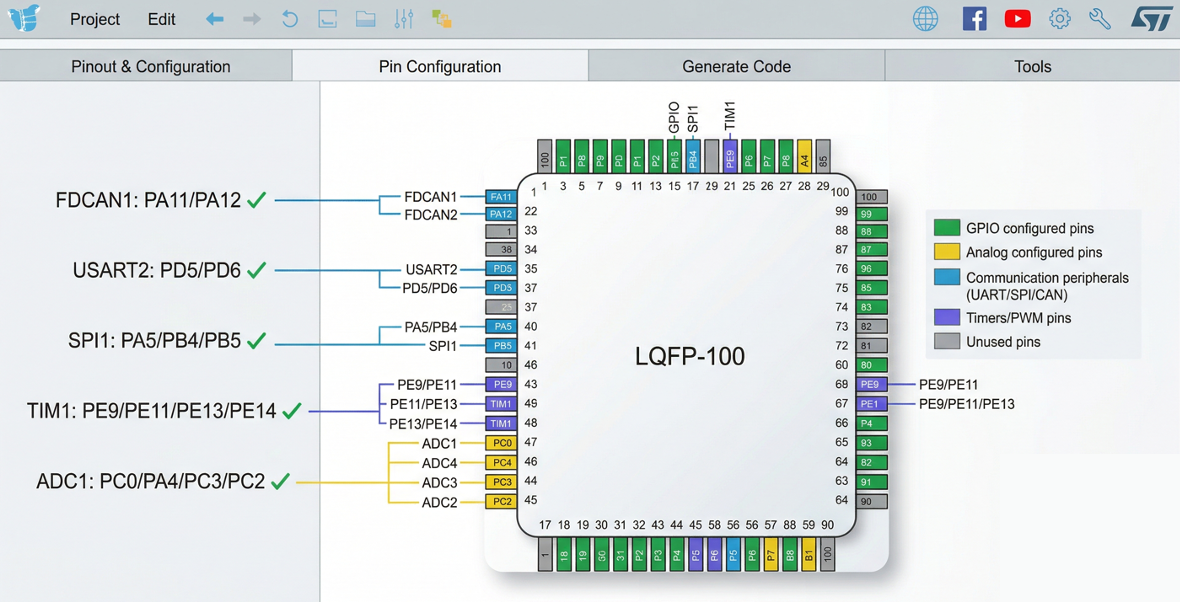 CubeMX pinout view
CubeMX is a tool that lets you configure STM32 pin assignments, clocks, and peripherals through a GUI and automatically generates the initialization code. It is built into STM32CubeIDE.
Step 1: Create Project & Select Chip
- STM32CubeIDE → File → New → STM32 Project
- In the MCU/MPU Selector tab, search:
STM32H743VITx - Select the chip and click Next
- Project Name:
AR_Walker_STM32(orH-Walker_STM32_Test) - Targeted Language: C
- Targeted Binary Type: Executable
- Targeted Project Type: STM32Cube
- Click Finish → the
.iocfile opens and the pin configuration view appears
Step 2: Assign Pins (Pinout & Configuration)
Click a pin in the chip graphic inside the .ioc editor to assign its function.
Recommended configuration order:
- Reserve debug pins: System Core → SYS → Debug: Serial Wire (PA13/PA14 auto-assigned)
- Clock source: System Core → RCC → HSE: Crystal/Ceramic Resonator
- FDCAN1: Connectivity → FDCAN1 → Activated
- TX: PD1, RX: PD0 (auto-assigned or selected manually)
- UART (IMU): Connectivity → UART4 → Mode: Asynchronous
- RX: PA1 (disable TX if not needed)
- UART (Debug): Connectivity → USART3 → Mode: Asynchronous
- TX: PD8, RX: PD9
- SPI1: Connectivity → SPI1 → Mode: Full-Duplex Master
- SCK: PA5, MOSI: PB5, MISO: PB4 (leave PA6/PA7 free for ADC)
- ADC1: Analog → ADC1 → Enable IN0, IN1, IN2, IN6 (or IN14/IN15)
- Watch for PA0/PA1 conflicts with UART4 RX; reassign ADC channels if needed
- TIM1 PWM: Timers → TIM1 → CH1: PWM Generation, CH2: PWM Generation
- CH1: PE9, CH2: PE11
- GPIO outputs: Click a pin → select GPIO_Output
- LED, Motor Enable, Motor Stop pins
- GPIO inputs: Motor error pins, etc.
Checking for pin conflicts:
- A yellow pin in CubeMX = warning (can be resolved)
- A red pin = conflict (must be fixed)
- Check the "Pinout Conflict" message in the left panel
Step 3: Clock Configuration
- Click the Clock Configuration tab at the top
- Left side — Input frequency: 8 (MHz, match your crystal)
- PLL Source Mux: select HSE
- Enter DIVM1: 1, DIVN1: 120, DIVP1: 2
- System Clock Mux: select PLLCLK
- Confirm HCLK reads 240 MHz (calculated automatically)
- Verify each APB clock is at 120 MHz
- If there are red warnings, click "Resolve Clock Issues"
Step 4: Peripheral Parameter Settings
Configure each peripheral in detail from the Configuration panel on the left.
FDCAN1 Parameters
Mode                    : Normal
Frame Format            : Classic (CAN 2.0)
Auto Retransmission     : Enable
Nominal Prescaler       : 10
Nominal Sync Jump Width : 1
Nominal Time Seg1       : 5
Nominal Time Seg2       : 6
→ Bit Rate = 120MHz / (10 × (1+5+6)) = 1 Mbps
ADC1 Parameters
Clock Prescaler         : Asynchronous clock mode divided by 4
Resolution              : ADC 12-bit resolution (or 16-bit)
Scan Conversion Mode    : Enable
Continuous Conv Mode    : Enable
DMA Continuous Requests : Enable
Number of Conversion    : (number of channels in use)
DMA Settings
In the DMA Settings tab of each peripheral:
- ADC1 → Add DMA Stream → Mode: Circular
- UART4_RX → Add DMA Stream → Mode: Circular
NVIC (Interrupt Priorities)
Interrupt          Priority (0=highest)  Purpose
FDCAN1_IT0         1                     CAN receive (motor response — top priority)
TIM6_DAC           2                     Control loop timer (500 Hz)
DMA_ADCx           3                     ADC conversion complete
UART4_IRQn         4                     IMU data receive
SPI1_IRQn          5                     Coms MCU data
EXTI_IRQn          6                     GPIO interrupt (errors, etc.)
Step 5: Project Settings
- Click the Project Manager tab
- Project Settings:
- Toolchain: STM32CubeIDE
- Generate Under Root: checked
- Code Generator:
- "Generate peripheral initialization as a pair of '.c/.h' files per peripheral" → check (recommended)
- "Keep User Code when re-generating" → check (required!)
- "Delete previously generated files when not re-generated" → check
Step 6: Generate Code
- Project → Generate Code (or Alt+K / Cmd+K)
- The generated file structure:
AR_Walker_STM32/
├── Core/
│   ├── Inc/
│   │   ├── main.h              ← GPIO pin defines (auto-generated by CubeMX)
│   │   ├── stm32h7xx_hal_conf.h
│   │   └── stm32h7xx_it.h
│   └── Src/
│       ├── main.c              ← ★ write your main code here
│       ├── stm32h7xx_hal_msp.c ← peripheral MSP initialization
│       └── stm32h7xx_it.c      ← interrupt handlers
├── Drivers/
│   ├── CMSIS/                  ← ARM core headers
│   └── STM32H7xx_HAL_Driver/   ← HAL library
└── STM32H743VITX_FLASH.ld      ← linker script
USER CODE Block Rules
These regions are preserved when CubeMX regenerates code:
/* USER CODE BEGIN Includes */
#include "motor_control.h"    // ✅ safe!
/* USER CODE END Includes */

// ❌ Writing here will be deleted on regeneration!

/* USER CODE BEGIN 0 */
void my_init(void) { }        // ✅ safe!
/* USER CODE END 0 */
Best practice: Create separate
.cfiles underCore/Src/for your own code. Examples:motor_control.c,sensor_read.c,can_protocol.c→ CubeMX never touches these files, so they are 100% safe. (See the "Managing Auto-Generated and User Code" section in README.md for details.)

Henry — Robot Education Founder
Engineer dedicated to democratizing robot education for everyone. From hardware bring-up to AI integration, I document real learning.
Comments
Loading comments...