STM32 GPIO Configuration — Push-Pull, Open-Drain, Speed, Pull-up/Pull-down
Complete guide to STM32 GPIO modes (Input/Output/AF/Analog), Push-Pull vs Open-Drain, speed settings, and pull-up/pull-down configuration.
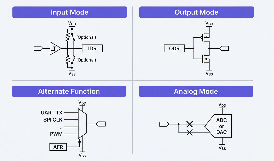 GPIO Input/Output/AF/Analog mode comparison
4.1 The Four GPIO Modes
Every GPIO pin is configured in one of four modes:
| Mode | MODER Value | Description | Example Use |
|---|---|---|---|
| Input | 00 | Read external signals | Buttons, motor error pins, interrupt inputs |
| Output | 01 | Drive signals out | LEDs, motor Enable, Motor Stop |
| Alternate Function | 10 | Connect pin to a peripheral | UART TX/RX, SPI, CAN, PWM |
| Analog | 11 | Analog input/output | ADC input (torque sensor, angle sensor), DAC |
4.2 Output Type: Push-Pull vs Open-Drain
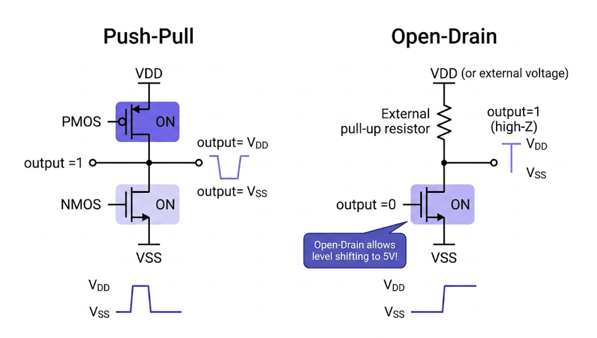 Push-Pull and Open-Drain output comparison
When in Output or AF mode, you choose the output type:
Push-Pull (PP):
VDD ─── [P-FET] ─┬── pin output
                  │
GND ─── [N-FET] ─┘

Output HIGH → P-FET ON, N-FET OFF → drives VDD (3.3V)
Output LOW  → P-FET OFF, N-FET ON → drives GND (0V)
- Actively drives both HIGH and LOW
- Use Push-Pull in most cases (LEDs, SPI, UART TX, PWM, etc.)
Open-Drain (OD):
         ┌── external pull-up resistor ── VDD (or 5V!)
pin ─────┤
         └── [N-FET] ── GND

Output LOW  → N-FET ON → drives GND
Output HIGH → N-FET OFF → pulled up to VDD by external resistor
- Only actively drives LOW; HIGH relies on an external pull-up
- Required for I2C (SDA/SCL)
- Level shifting: use when a 3.3V MCU communicates with 5V devices
4.3 Pull Configuration
| Setting | Effect | When to Use |
|---|---|---|
| No Pull | No pull-up or pull-down | AF mode (peripheral controls the line), when external pull-up/down is present |
| Pull-Up | Internal ~40kΩ resistor to VDD | Button inputs (active-low), UART RX idle state |
| Pull-Down | Internal ~40kΩ resistor to GND | Prevent floating pins, when a default-LOW state is needed |
4.4 Output Speed
| Speed | Max Frequency | When to Use |
|---|---|---|
| Low | ~12 MHz | GPIO toggling (LEDs), low-speed signals |
| Medium | ~60 MHz | UART, I2C |
| High | ~85 MHz | SPI, SDMMC |
| Very High | ~100 MHz | High-speed SPI, FMC |
⚠️ Rule: Always choose the minimum speed required. Higher speeds increase EMI (electromagnetic interference) and current consumption.
- LED, Enable pins → Low
- CAN, UART → Medium
- SPI → High or Very High
4.5 GPIO Configuration with the HAL Library
Structure of the code auto-generated by CubeMX:
/* Core/Src/main.c — inside MX_GPIO_Init() */

static void MX_GPIO_Init(void)
{
    GPIO_InitTypeDef GPIO_InitStruct = {0};

    /* Enable GPIO port clocks */
    __HAL_RCC_GPIOA_CLK_ENABLE();
    __HAL_RCC_GPIOB_CLK_ENABLE();
    __HAL_RCC_GPIOC_CLK_ENABLE();
    __HAL_RCC_GPIOD_CLK_ENABLE();
    __HAL_RCC_GPIOE_CLK_ENABLE();

    /* === Example 1: LED output (PB0) === */
    HAL_GPIO_WritePin(GPIOB, GPIO_PIN_0, GPIO_PIN_RESET);  // initial state LOW
    GPIO_InitStruct.Pin   = GPIO_PIN_0;
    GPIO_InitStruct.Mode  = GPIO_MODE_OUTPUT_PP;    // Output Push-Pull
    GPIO_InitStruct.Pull  = GPIO_NOPULL;            // no pull-up/pull-down
    GPIO_InitStruct.Speed = GPIO_SPEED_FREQ_LOW;    // low speed (it's an LED)
    HAL_GPIO_Init(GPIOB, &GPIO_InitStruct);

    /* === Example 2: Button input + interrupt (PC13) === */
    GPIO_InitStruct.Pin   = GPIO_PIN_13;
    GPIO_InitStruct.Mode  = GPIO_MODE_IT_FALLING;   // falling edge interrupt
    GPIO_InitStruct.Pull  = GPIO_PULLUP;             // internal pull-up
    HAL_GPIO_Init(GPIOC, &GPIO_InitStruct);

    /* Enable EXTI interrupt */
    HAL_NVIC_SetPriority(EXTI15_10_IRQn, 5, 0);
    HAL_NVIC_EnableIRQ(EXTI15_10_IRQn);

    /* === Example 3: Motor Enable pin (PD3) === */
    HAL_GPIO_WritePin(GPIOD, GPIO_PIN_3, GPIO_PIN_RESET);
    GPIO_InitStruct.Pin   = GPIO_PIN_3;
    GPIO_InitStruct.Mode  = GPIO_MODE_OUTPUT_PP;
    GPIO_InitStruct.Pull  = GPIO_PULLDOWN;           // default OFF (safe state)
    GPIO_InitStruct.Speed = GPIO_SPEED_FREQ_LOW;
    HAL_GPIO_Init(GPIOD, &GPIO_InitStruct);
}
4.6 GPIO Control Functions
/* Set pin HIGH */
HAL_GPIO_WritePin(GPIOB, GPIO_PIN_0, GPIO_PIN_SET);

/* Set pin LOW */
HAL_GPIO_WritePin(GPIOB, GPIO_PIN_0, GPIO_PIN_RESET);

/* Toggle pin */
HAL_GPIO_TogglePin(GPIOB, GPIO_PIN_0);

/* Read pin */
GPIO_PinState state = HAL_GPIO_ReadPin(GPIOC, GPIO_PIN_13);
if (state == GPIO_PIN_SET) {
    // pin is HIGH
}
4.7 Exercise: Blinking an LED (First Sanity Check)
The first test to run after assembling the board:
/* Core/Src/main.c */

/* USER CODE BEGIN Includes */
/* USER CODE END Includes */

int main(void)
{
    HAL_Init();
    SystemClock_Config();
    MX_GPIO_Init();

    /* USER CODE BEGIN 2 */
    // (additional init code)
    /* USER CODE END 2 */

    while (1)
    {
        /* USER CODE BEGIN 3 */
        HAL_GPIO_TogglePin(GPIOB, GPIO_PIN_0);  // toggle LED
        HAL_Delay(500);                           // wait 500ms
        /* USER CODE END 3 */
    }
}
If the LED blinks every 0.5 seconds, you have confirmed:
- Power is good (VDD 3.3V)
- Clock is good (HSE → PLL → SYSCLK)
- GPIO is working (output functional)
- HAL library is working (HAL_Delay works = SysTick is running)
- Flash programming succeeded (code is executing)

Henry — Robot Education Founder
Engineer dedicated to democratizing robot education for everyone. From hardware bring-up to AI integration, I document real learning.
Comments
Loading comments...