STM32 Clock System — HSE, PLL, and Clock Tree Configuration
Understanding STM32H7 clock sources (HSE/HSI), PLL configuration, and how to set up the clock tree for 480MHz.
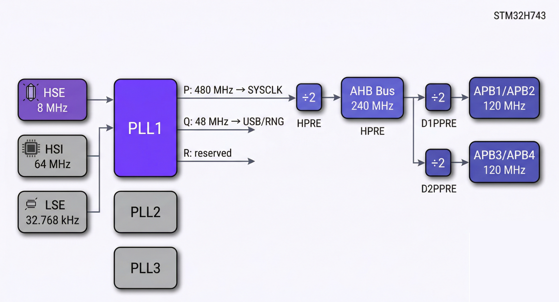 HSE → PLL → SYSCLK clock tree
3.1 Clock Sources
The STM32H743 has four clock sources:
| Clock Source | Frequency | Accuracy | Usage |
|---|---|---|---|
| HSE (High-Speed External) | 4~50 MHz (typically 8 or 25 MHz) | High (crystal) | PLL input → SYSCLK |
| HSI (High-Speed Internal) | 64 MHz fixed | Moderate (RC oscillator) | Default clock after reset |
| LSE (Low-Speed External) | 32.768 kHz | High | RTC, low-power modes |
| LSI (Low-Speed Internal) | 32 kHz | Low | Independent watchdog (IWDG) |
Choice for the robot board:
- Recommended: HSE 8MHz crystal → generates 480MHz SYSCLK via PLL
- LSE 32.768kHz is optional (only if RTC is needed)
- HSI is a fallback (can auto-switch if crystal fails)
3.2 PLL Configuration: Path from 8MHz to 480MHz
The STM32H7 has three PLLs. PLL1 (main) generates SYSCLK:
HSE (8 MHz)
    │
    ▼
  DIVM1 = /1        ← PLL input prescaler
    │
    ▼
  8 MHz (PLL input)  ← must be within 1~16 MHz range
    │
    ▼
  DIVN1 = x120      ← VCO multiplier
    │
    ▼
  960 MHz (VCO)     ← VCO range: 192~960 MHz
    │
    ├─ DIVP1 = /2 ──→ 480 MHz ──→ SYSCLK (system clock)
    │
    ├─ DIVQ1 = /4 ──→ 240 MHz ──→ some peripherals (FDCAN, etc.)
    │
    └─ DIVR1 = /2 ──→ 480 MHz ──→ (disable if unused)
CubeMX settings:
| Parameter | Value | Meaning |
|---|---|---|
| PLL Source | HSE | Use external crystal |
| DIVM1 | 1 | 8MHz / 1 = 8MHz |
| DIVN1 | 120 | 8MHz x 120 = 960MHz (VCO) |
| DIVP1 | 2 | 960MHz / 2 = 480MHz (SYSCLK) |
| DIVQ1 | 4 | 960MHz / 4 = 240MHz |
| DIVR1 | 2 | 960MHz / 2 = 480MHz (can be disabled) |
3.3 Clock Tree: Distribution from SYSCLK to Each Bus
SYSCLK (480 MHz)
    │
    ▼
  D1CPRE = /1
    │
    ▼
  CPU clock = 480 MHz
    │
    ├── HPRE = /2 ──→ AHB clock = 240 MHz
    │                    │
    │                    ├── D1PPRE = /2 ──→ APB3 = 120 MHz (timers x2 = 240 MHz)
    │                    │
    │                    ├── D2PPRE1 = /2 ──→ APB1 = 120 MHz (timers x2 = 240 MHz)
    │                    │                      └── TIM2-7, TIM12-14
    │                    │                      └── USART2/3, UART4/5/7/8
    │                    │                      └── SPI2/3, I2C1-3
    │                    │                      └── **FDCAN1/2**
    │                    │
    │                    ├── D2PPRE2 = /2 ──→ APB2 = 120 MHz (timers x2 = 240 MHz)
    │                    │                      └── TIM1, TIM8, TIM15-17
    │                    │                      └── USART1/6
    │                    │                      └── SPI1/4/5
    │                    │                      └── ADC1/2
    │                    │
    │                    └── D3PPRE = /2 ──→ APB4 = 120 MHz
    │                                        └── I2C4, SPI6
    │                                        └── EXTI, RTC
    │
    └── SysTick = 480 MHz (default) or AHB/8
Key summary:
| Bus | Frequency | Timer Clock | Key Peripherals |
|---|---|---|---|
| CPU | 480 MHz | — | Cortex-M7 core |
| AHB | 240 MHz | — | DMA, GPIO, Flash |
| APB1 | 120 MHz | 240 MHz | FDCAN, UART4/5/7/8, SPI2/3, TIM2-7 |
| APB2 | 120 MHz | 240 MHz | USART1/6, SPI1, ADC1/2, TIM1/8 |
| APB3 | 120 MHz | — | LTDC |
| APB4 | 120 MHz | — | I2C4, SPI6 |
🔴 Important: Timers connected to an APB bus are automatically doubled (x2) when the APB prescaler is not 1. Since APB1 = 120MHz with a /2 prescaler, the actual clock for TIM2~7 is 240MHz.
3.4 Clock Configuration in CubeMX
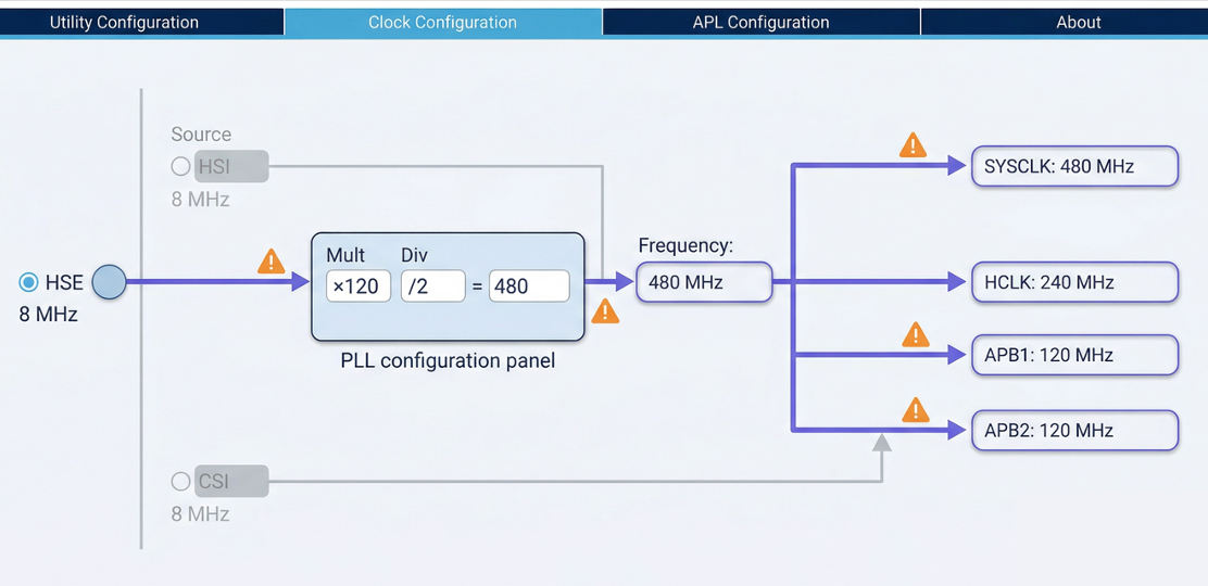 CubeMX Clock Configuration tab
In the CubeMX Clock Configuration tab:
- Left side: Select "HSE" in the PLL Source Mux
- Middle: Enter PLL1 parameters (DIVM=1, N=120, P=2, Q=4)
- System Clock Mux: Select "PLLCLK"
- Right side: Bus prescalers are configured automatically
- Verify: Click "Resolve Clock Issues" to check for problems
If CubeMX shows red, the frequency exceeds the maximum for that bus. Adjust the prescalers to bring each bus frequency within its allowed maximum.

Henry — Robot Education Founder
Engineer dedicated to democratizing robot education for everyone. From hardware bring-up to AI integration, I document real learning.
Comments
Loading comments...